Class diagram with staruml 8
Table of Contents
Table of Contents
If you’re a software developer or a system analyst, you know the importance of designing diagrams during the development process. One of the most widely used diagrams is the activity diagram. In this post, we’ll discuss how to draw activity diagrams using StarUML, a popular software modeling tool.
Developers and system analysts often face challenges in designing activity diagrams using StarUML. The process can be complex, and there are several nuances that need to be considered. But with a little practice, you can master the art of designing activity diagrams using StarUML.
Activity diagrams are used to illustrate business processes and workflows in software development. They provide a visual representation of how different tasks and activities are connected and how software works. In StarUML, you can design activity diagrams using a vast array of tools and options.
To draw an activity diagram in StarUML, you need to follow a few basic steps. Firstly, open a new project and go to the ‘Add Diagram’ option. Select ‘Activity Diagram’ from the list of available diagrams. Next, you’ll need to define the starting point of your diagram. Simply click on the ‘Initial Node’ option from the sidebar and drag it to your diagram. You can then add additional task nodes and connect them using various control nodes available in StarUML.
My Experience with Drawing Activity Diagrams Using StarUML
When I was first learning how to create activity diagrams using StarUML, I found the process to be overwhelming. There were so many options and tools available that it was challenging to know where to start. However, with a bit of practice, I quickly became comfortable with the software and was able to create intricate diagrams in no time.
Understanding Control Nodes in Activity Diagrams Using StarUML
Control nodes are an essential element of activity diagrams in StarUML. These nodes are used to control the flow of activities and provide decision-making capabilities. There are several types of control nodes available in StarUML, including ‘Fork,’ ‘Join,’ ‘Decision,’ and ‘Merge.’ Understanding these nodes’ functionality is crucial in creating an effective activity diagram.
Decision Nodes in Activity Diagrams Using StarUML
Decision nodes are used to show the decision-making process in an activity diagram. These nodes are represented by a diamond-shaped box and allow the designer to connect two or more paths based on specific conditions. To create a decision node in StarUML, simply select the ‘Decision’ node from the sidebar and drag it to your diagram. You can then connect various actions and nodes to the decision node, depending on the conditions.
Creating Multiple Paths Using Fork Nodes in Activity Diagrams Using StarUML
Fork nodes are used to create multiple paths from a single point in an activity diagram. This node allows you to split the flow of activities into multiple concurrent paths, representing different task flows. To create a fork node, select the ‘Fork’ option from the sidebar and drag it to your diagram. You can then connect various nodes to the fork node, creating a parallel path for different activities.
Question and Answer
Q: How do you add a new activity to the diagram?
A: You can add a new activity to the diagram by selecting the ‘Activity’ option from the sidebar and dragging it to your diagram. You can then rename the activity and add any necessary details.
Q: Can you add notes to an activity diagram using StarUML?
A: Yes, you can add notes to an activity diagram in StarUML. Simply select the ‘Note’ option from the sidebar and drag it to your diagram. You can then add any necessary notes or information to the note box.
Q: How do you group multiple elements in an activity diagram?
A: You can group multiple elements in an activity diagram by selecting them and clicking the ‘Group’ option from the toolbar. This will group the elements together, allowing you to move or resize them as a single entity.
Q: Can you export an activity diagram created using StarUML?
A: Yes, you can export an activity diagram created using StarUML. Simply select the ‘Export Diagram as Image’ option from the toolbar and choose the desired file format and location.
Conclusion of How to Draw Activity Diagram Using StarUML
Creating activity diagrams using StarUML can be a challenging process, but with dedication and practice, you can master the art of designing complex diagrams. By using the right tools and control nodes, you can develop clear and concise diagrams that represent your software development process effectively.
Gallery
What Are Steps To Create Er Diagram In Staruml | ERModelExample.com

Photo Credit by: bing.com / staruml uml component sequence ermodelexample flexibility
Staruml Menggunakan Class Diagram | Porn Sex Picture

Photo Credit by: bing.com /
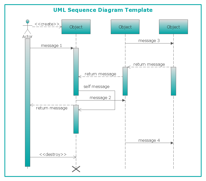
Staruml Sequence Diagram

Photo Credit by: bing.com / diagram sequence staruml draw using uml star fragment example model object diagaram
What Are Steps To Create Er Diagram In Staruml | ERModelExample.com

Photo Credit by: bing.com / staruml sequence flowchart gis erd ermodelexample
Class Diagram With StarUML [8] | Download Scientific Diagram
![Class diagram with StarUML [8] | Download Scientific Diagram](https://www.researchgate.net/profile/Daouda-Kamissoko/publication/260138133/figure/fig2/AS:392462922207233@1470581860240/Class-diagram-with-StarUML-8_Q640.jpg "Class diagram with StarUML [8] | Download Scientific Diagram")
Photo Credit by: bing.com / staruml